Targets
This chapter describes configuration of supported targets.
Supported Targets
- Cortex-A53 / Raspberry PI 3
- Cypress PSoC-6
- Microchip SAME51
- Nordic nRF52840
- NXP LPC54xxx
- NXP iMX-RT
- NXP Kinetis
- NXP P1021 PPC
- NXP T1024 PPC
- NXP T2080 PPC
- NXP MCXA153
- SiFive HiFive1 RISC-V
- STM32F4
- STM32F7
- STM32L0
- STM32L4
- STM32L5
- STM32G0
- STM32C0
- STM32H5
- STM32H7
- STM32U5
- STM32WB55
- TI Hercules TMS570LC435
- Xilinx Zynq UltraScale
- Renesas RX65N
- Renesas RX72N
- Renesas RA6M4
- Renesas RZN2L
- Qemu x86-64 UEFI
- Intel x86-64 Intel FSP
STM32F4
Example 512KB partitioning on STM32-F407
The example firmware provided in the test-app is configured to boot from the primary partition
starting at address 0x20000. The flash layout is provided by the default example using the following
configuration in target.h:
#define WOLFBOOT_SECTOR_SIZE              0x20000
#define WOLFBOOT_PARTITION_SIZE           0x20000

#define WOLFBOOT_PARTITION_BOOT_ADDRESS   0x20000
#define WOLFBOOT_PARTITION_UPDATE_ADDRESS 0x40000
#define WOLFBOOT_PARTITION_SWAP_ADDRESS   0x60000
This results in the following partition configuration:
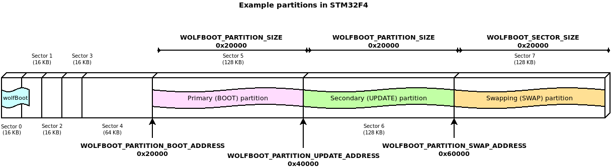
This configuration demonstrates one of the possible layouts, with the slots aligned to the beginning of the physical sector on the flash.
The entry point for all the runnable firmware images on this target will be 0x20100,
256 Bytes after the beginning of the first flash partition. This is due to the presence
of the firmware image header at the beginning of the partition, as explained more in details
in Firmware image
In this particular case, due to the flash geometry, the swap space must be as big as 128KB, to account for proper sector swapping between the two images.
On other systems, the SWAP space can be as small as 512B, if multiple smaller flash blocks are used.
More information about the geometry of the flash and in-application programming (IAP) can be found in the manufacturer manual of each target device.
STM32F4 Programming
st-flash write factory.bin 0x08000000
STM32F4 Debugging
- Start GDB server
OpenOCD: openocd --file ./config/openocd/openocd_stm32f4.cfg
OR
ST-Link: st-util -p 3333
- Start GDB Client
arm-none-eabi-gdb
add-symbol-file test-app/image.elf 0x20100
mon reset init
b main
c
STM32L4
Example 1MB partitioning on STM32L4
- Sector size: 4KB
- Wolfboot partition size: 40 KB
- Application partition size: 488 KB
#define WOLFBOOT_SECTOR_SIZE                 0x1000   /* 4 KB */
#define WOLFBOOT_PARTITION_BOOT_ADDRESS      0x0800A000
#define WOLFBOOT_PARTITION_SIZE              0x7A000  /* 488 KB */
#define WOLFBOOT_PARTITION_UPDATE_ADDRESS    0x08084000
#define WOLFBOOT_PARTITION_SWAP_ADDRESS      0x080FE000
STM32L5
Scenario 1: TrustZone Enabled
Example Description
The implementation shows how to switch from secure application to non-secure application, thanks to the system isolation performed, which splits the internal Flash and internal SRAM memories into two parts: - the first half is used by wolfboot running in secure mode and the secure application - the remaining available space is used for non-secure application and update partition
The example configuration for this scenario is available in /config/examples/stm32l5.config.
Hardware and Software environment
- This example runs on STM32L562QEIxQ devices with security enabled (TZEN=1).
- This example has been tested with STMicroelectronics STM32L562E-DK (MB1373)
- User Option Bytes requirement (with STM32CubeProgrammer tool - see below for instructions)
TZEN = 1                            System with TrustZone-M enabled
DBANK = 1                           Dual bank mode
SECWM1_PSTRT=0x0  SECWM1_PEND=0x7F  All 128 pages of internal Flash Bank1 set as secure
SECWM2_PSTRT=0x1  SECWM2_PEND=0x0   No page of internal Flash Bank2 set as secure, hence Bank2 non-secure
- NOTE: STM32CubeProgrammer V2.3.0 is required (v2.4.0 has a known bug for STM32L5)
How to use it
cp ./config/examples/stm32l5.config .configmake- Prepare board with option bytes configuration reported above
STM32_Programmer_CLI -c port=swd mode=hotplug -ob TZEN=1 DBANK=1STM32_Programmer_CLI -c port=swd mode=hotplug -ob SECWM1_PSTRT=0x0 SECWM1_PEND=0x7F SECWM2_PSTRT=0x1 SECWM2_PEND=0x0
- flash wolfBoot.bin to 0x0c00 0000
STM32_Programmer_CLI -c port=swd -d ./wolfboot.bin 0x0C000000
- flash
.\test-app\image_v1_signed.binto 0x0804 0000STM32_Programmer_CLI -c port=swd -d ./test-app/image_v1_signed.bin 0x08040000
-
RED LD9 will be on
-
NOTE: STM32_Programmer_CLI Default Locations
- Windows:
C:\Program Files\STMicroelectronics\STM32Cube\STM32CubeProgrammer\bin\STM32_Programmer_CLI.exe - Linux:
/usr/local/STMicroelectronics/STM32Cube/STM32CubeProgrammer/bin/STM32_Programmer_CLI - Mac OS/X:
/Applications/STMicroelectronics/STM32Cube/STM32CubeProgrammer/STM32CubeProgrammer.app/Contents/MacOs/bin/STM32_Programmer_CLI
Scenario 2: Trustzone Enabled, wolfCrypt as secure engine for NS applications
This is similar to Scenario 1, but also includes wolfCrypt in secure mode, and that can be accessed via PKCS11 interface by non-secure applications.
This option can be enabled with the WOLFCRYPT_TZ=1 and WOLFCRYPT_TZ_PKCS11=1
options in your configuration. This enables a PKCS11 accessible from NS domain via
non-secure callables (NSC).
The example configuration for this scenario is available in /config/examples/stm32l5-wolfcrypt-tz.config.
For more information, see Appendix L.
Scenario 3: Trustzone Disabled, using DUAL BANK
Example Description
The implementation shows how to use STM32L5xx in DUAL BANK mode, with TrustZone disabled. The DUAL_BANK option is only available on this target when TrustZone is disabled (TZEN = 0).
The flash memory is segmented into two different banks:
- Bank 0: (0x08000000)
- Bank 1: (0x08040000)
Bank 0 contains the bootloader at address 0x08000000, and the application at address 0x08040000. When a valid image is available at the same offset in Bank 1, a candidate is selected for booting between the two valid images. A firmware update can be uploaded at address 0x08048000.
The example configuration is available in /config/examples/stm32l5-nonsecure-dualbank.config.
To run flash ./test-app/image.bin to 0x08000000.
- STM32_Programmer_CLI -c port=swd -d ./test-app/image.bin 0x08000000
Or program each partition using:
1. flash wolfboot.bin to 0x08000000:
- STM32_Programmer_CLI -c port=swd -d ./wolfboot.elf
2. flash main application to 0x0800 a000
- STM32_Programmer_CLI -c port=swd -d ./test-app/image_v1_signed.bin 0x0800a000
RED LD9 will be on indicating successful boot ().
Updates can be flashed at 0x0804a000:
STM32_Programmer_CLI -c port=swd -d ./test-app/image_v2_signed.bin 0x0804a000
The two partition are logically remapped by using BANK_SWAP capabilities. This partition swap is immediate and does not require a SWAP partition.
Debugging
Use make DEBUG=1 and reload firmware.
- STM32CubeIDE v.1.3.0 required
- Run the debugger via:
Linux:
ST-LINK_gdbserver -d -cp /opt/st/stm32cubeide_1.3.0/plugins/\
com.st.stm32cube.ide.mcu.externaltools.cubeprogrammer.\
linux64_1.3.0.202002181050/tools/bin -e -r 1 -p 3333
Mac OS/X:
sudo ln -s /Applications/STM32CubeIDE.app/Contents/Eclipse/plugins\
/com.st.stm32cube.ide.mcu.externaltools.\
stlink-gdb-server.macos64_1.6.0.202101291314/\
tools/bin/native/mac_x64/libSTLinkUSBDriver.dylib \
/usr/local/lib/libSTLinkUSBDriver.dylib

/Applications/STM32CubeIDE.app/Contents/Eclipse/plugins/\
com.st.stm32cube.ide.mcu.externaltools.\
stlink-gdb-server.macos64_1.6.0.202101291314/tools/bin/\
ST-LINK_gdbserver -d -cp ./Contents/Eclipse/plugins/\
com.st.stm32cube.ide.mcu.externaltools.cubeprogrammer.\
macos64_1.6.0.202101291314/tools/bin -e -r 1 -p 3333
- Connect with arm-none-eabi-gdb
wolfBoot has a .gdbinit to configure
arm-none-eabi-gdb
add-symbol-file test-app/image.elf
mon reset init
STM32U5
The STM32U5 is a Cortex-M33 (ARMv8-M).
Note: We have seen issues with vector table alignment, so the default image header size (IMAGE_HEADER_SIZE) has been increased to 1024 bytes to avoid potential issues.
Scenario 1: TrustZone enabled, staging non-secure application
Example description
The implementation shows how to switch from secure application to non-secure application, thanks to the system isolation performed, which splits the internal Flash and internal SRAM memories into two parts: - the first 256KB are used by wolfboot running in secure mode and the secure application - the remaining available space is used for non-secure application and update partition
The example configuration for this scenario is available in /config/examples/stm32u5.config.
Example Description
The implementation shows how to switch from secure application to non-secure application, thanks to the system isolation performed, which splits the internal Flash and internal SRAM memories into two parts: - the first half for secure application - the second half for non-secure application
Hardware and Software environment
- This example runs on STM32U585AII6Q devices with security enabled (TZEN=1).
- This example has been tested with STMicroelectronics B-U585I-IOT02A (MB1551)
- User Option Bytes requirement (with STM32CubeProgrammer tool - see below for instructions)
TZEN = 1                            System with TrustZone-M enabled
DBANK = 1                           Dual bank mode
SECWM1_PSTRT=0x0  SECWM1_PEND=0x7F  All 128 pages of internal Flash Bank1 set as secure
SECWM2_PSTRT=0x1  SECWM2_PEND=0x0   No page of internal Flash Bank2 set as secure, hence Bank2 non-secure
- NOTE: STM32CubeProgrammer V2.8.0 or newer is required
How to use it
cp ./config/examples/stm32u5.config .configmake TZEN=1- Prepare board with option bytes configuration reported above
STM32_Programmer_CLI -c port=swd mode=hotplug -ob TZEN=1 DBANK=1STM32_Programmer_CLI -c port=swd mode=hotplug -ob SECWM1_PSTRT=0x0 SECWM1_PEND=0x7F SECWM2_PSTRT=0x1 SECWM2_PEND=0x0
- flash wolfBoot.bin to 0x0c000000
STM32_Programmer_CLI -c port=swd -d ./wolfboot.bin 0x0C000000
- flash
.\test-app\image_v1_signed.binto 0x08010000STM32_Programmer_CLI -c port=swd -d ./test-app/image_v1_signed.bin 0x08100000
-
RED LD9 will be on
-
NOTE: STM32_Programmer_CLI Default Locations
- Windows:
C:\Program Files\STMicroelectronics\STM32Cube\STM32CubeProgrammer\bin\STM32_Programmer_CLI.exe - Linux:
/usr/local/STMicroelectronics/STM32Cube/STM32CubeProgrammer/bin/STM32_Programmer_CLI - Mac OS/X:
/Applications/STMicroelectronics/STM32Cube/STM32CubeProgrammer/STM32CubeProgrammer.app/Contents/MacOs/bin/STM32_Programmer_CLI
Scenario 2: TrustZone Enabled, wolfCrypt as secure engine for NS applications
This is similar to Scenario 1, but also includes wolfCrypt in secure mode, and that can be accessed via PKCS11 interface by non-secure applications.
This option can be enabled with the WOLFCRYPT_TZ=1 and WOLFCRYPT_TZ_PKCS11=1
options in your configuration. This enables a PKCS11 accessible from NS domain via
non-secure callables (NSC).
The example configuration for this scenario is available in /config/examples/stm32u5-wolfcrypt-tz.config.
For more information, see Appendix L.
Scenario 3: TrustZone Disabled (DUAL BANK mode)
Example Description
The implementation shows how to use STM32U5xx in DUAL_BANK mode, with TrustZone disabled. The DUAL_BANK option is only available on this target when TrustZone is disabled (TZEN = 0).
The flash memory is segmented into two different banks:
- Bank 0: (0x08000000)
- Bank 1: (0x08100000)
Bank 0 contains the bootloader at address 0x08000000, and the application at address 0x08100000. When a valid image is available at the same offset in Bank 1, a candidate is selected for booting between the two valid images. A firmware update can be uploaded at address 0x08108000.
The example configuration is available in config/examples/stm32u5-nonsecure-dualbank.config.
Program each partition using:
1. flash wolfboot.bin to 0x08000000:
- STM32_Programmer_CLI -c port=swd -d ./wolfboot.bin 0x08000000
2. flash image_v1_signed.bin to 0x08008000
- STM32_Programmer_CLI -c port=swd -d ./test-app/image_v1_signed.bin 0x08008000
RED LD9 will be on indicating successful boot ()
Debugging
Use make DEBUG=1 and reload firmware.
- STM32CubeIDE v.1.7.0 required
- Run the debugger via:
Linux:
ST-LINK_gdbserver -d -cp /opt/st/stm32cubeide_1.3.0/plugins/\
com.st.stm32cube.ide.mcu.externaltools.\
cubeprogrammer.linux64_1.3.0.202002181050/tools/bin -e -r 1 -p 3333`
Max OS/X:
/Applications/STM32CubeIDE.app/Contents/Eclipse/plugins/\
com.st.stm32cube.ide.mcu.externaltools.\
stlink-gdb-server.macos64_2.1.300.202403291623/tools/bin/\
ST-LINK_gdbserver -d -cp /Applications/STM32CubeIDE.app/\
Contents/Eclipse/plugins/com.st.stm32cube.ide.mcu.\
externaltools.cubeprogrammer.macos64_2.1.201.202404072231/tools/\
bin -e -r 1 -p 3333
Win:
ST-LINK_gdbserver -d -cp C:\ST\STM32CubeIDE_1.7.0\ ^
STM32CubeIDE\plugins\com.st.stm32cube.ide.mcu.externaltools. ^
cubeprogrammer.win32_2.0.0.202105311346\tools\bin -e -r 1 -p 3333`
- Connect with arm-none-eabi-gdb or gdb-multiarch
wolfBoot has a .gdbinit to configure
add-symbol-file test-app/image.elf
STM32L0
Example 192KB partitioning on STM32-L073
This device is capable of erasing single flash pages (256B each).
However, we choose to use a logic sector size of 4KB for the swaps, to limit the amount of writes to the swap partition.
The proposed geometry in this example target.h uses 32KB for wolfBoot, and two
partitions of 64KB each, leaving room for up to 8KB to use for swap (4K are being used here).
#define WOLFBOOT_SECTOR_SIZE                 0x1000   /* 4 KB */
#define WOLFBOOT_PARTITION_BOOT_ADDRESS      0x8000
#define WOLFBOOT_PARTITION_SIZE              0x10000 /* 64 KB */
#define WOLFBOOT_PARTITION_UPDATE_ADDRESS    0x18000
#define WOLFBOOT_PARTITION_SWAP_ADDRESS      0x28000
STM32L0 Building
Use make TARGET=stm32l0. The option CORTEX_M0 is automatically selected for this target.
STM32G0
Supports STM32G0x0x0/STM32G0x1.
Example 128KB partitioning on STM32-G070:
- Sector size: 2KB
- Wolfboot partition size: 32KB
- Application partition size: 44 KB
#define WOLFBOOT_SECTOR_SIZE                 0x800   /* 2 KB */
#define WOLFBOOT_PARTITION_BOOT_ADDRESS      0x08008000
#define WOLFBOOT_PARTITION_SIZE              0xB000  /* 44 KB */
#define WOLFBOOT_PARTITION_UPDATE_ADDRESS    0x08013000
#define WOLFBOOT_PARTITION_SWAP_ADDRESS      0x0801E000
Building STM32G0
Reference configuration (see /config/examples/stm32g0.config).
You can copy this to wolfBoot root as .config: cp ./config/examples/stm32g0.config .config.
To build you can use make.
The TARGET for this is stm32g0: make TARGET=stm32g0.
The option CORTEX_M0 is automatically selected for this target.
The option NVM_FLASH_WRITEONCE=1 is mandatory on this target, since the IAP driver does not support
multiple writes after each erase operation.
STM32G0 Secure Hide Protection Feature (Optional)
This part supports a "secure memory protection" feature makes the wolfBoot partition unaccessible after jump to application.
It uses the FLASH_CR:SEC_PROT and FLASH_SECT:SEC_SIZE registers. This is the
number of 2KB pages to block access to from the 0x8000000 base address.
Command example to enable this for 32KB bootloader:
STM32_Programmer_CLI -c port=swd mode=hotplug -ob SEC_SIZE=0x10
Enabled with CFLAGS_EXTRA+=-DFLASH_SECURABLE_MEMORY_SUPPORT.
Requires RAM_CODE=1 to enable RAMFUNCTION support.
STM32G0 Programming
Compile requirements: make TARGET=stm32g0 NVM_FLASH_WRITEONCE=1
The output is a single factory.bin that includes wolfboot.bin and test-app/image_v1_signed.bin combined together.
This should be programmed to the flash start address 0x08000000.
Flash using the STM32CubeProgrammer CLI:
STM32_Programmer_CLI -c port=swd -d factory.bin 0x08000000
STM32G0 Debugging
Use make DEBUG=1 and program firmware again.
Start GDB server on port 3333:
ST-LINK_gdbserver -d -e -r 1 -p 3333
OR
st-util -p 3333
wolfBoot has a .gdbinit to configure GDB
arm-none-eabi-gdb
add-symbol-file test-app/image.elf 0x08008100
mon reset init
STM32C0
Supports STM32C0x0/STM32C0x1. Instructions are for the STM Nucleo-C031C6 dev board.
Tested build configurations: * With RSA2048 and SHA2-256 the code size is 10988 and it boots in under 1 second. * With ED25519 and SHA2-384 the code size is 10024 and takes about 10 seconds for the LED to turn on. * With LMS-8-10-1 and SHA2-256 the code size is 8164 on gcc-13 (could fit in 8KB partition)
Example 32KB partitioning on STM32-G070
with ED25519 or LMS-8-10-1:
- Sector size: 2KB
- Wolfboot partition size: 10KB
- Application partition size: 10 KB
- Swap size 2KB
#define WOLFBOOT_SECTOR_SIZE                 0x800   /* 2 KB */
#define WOLFBOOT_PARTITION_BOOT_ADDRESS      0x08002800 /* at 10KB */
#define WOLFBOOT_PARTITION_SIZE              0x2800  /* 10 KB */
#define WOLFBOOT_PARTITION_UPDATE_ADDRESS    0x08005000 /* at 20KB */
#define WOLFBOOT_PARTITION_SWAP_ADDRESS      0x08007800 /* at 30KB */
with RSA2048:
- Sector size: 2KB
- Wolfboot partition size: 12KB
- Application partition size: 8 KB
- Swap size 2KB
#define WOLFBOOT_SECTOR_SIZE                 0x800      /* 2 KB */
#define WOLFBOOT_PARTITION_BOOT_ADDRESS      0x08003000 /* at 12KB */
#define WOLFBOOT_PARTITION_SIZE              0x2000     /* 8 KB */
#define WOLFBOOT_PARTITION_UPDATE_ADDRESS    0x08005000 /* at 20KB */
#define WOLFBOOT_PARTITION_SWAP_ADDRESS      0x08007800 /* at 30KB */
Building STM32C0
Reference configuration files (see config/examples/stm32c0.config,
config/examples/stm32c0-rsa2048.config and
config/examples/stm32c0-lms-8-10-1.config).
You can copy one of these to wolfBoot root as .config: cp ./config/examples/stm32c0.config .config.
To build you can use make.
The TARGET for this is stm32c0: make TARGET=stm32c0.
The option CORTEX_M0 is automatically selected for this target.
The option NVM_FLASH_WRITEONCE=1 is mandatory on this target, since the IAP driver does not support
multiple writes after each erase operation.
STM32C0 Secure Hide Protection Feature (Optional)
This part supports a "secure memory protection" feature makes the wolfBoot partition unaccessible after jump to application.
It uses the FLASH_CR:SEC_PROT and FLASH_SECT:SEC_SIZE registers. This is the
number of 2KB pages to block access to from the 0x8000000 base address.
Command example to enable this for 10KB bootloader:
STM32_Programmer_CLI -c port=swd mode=hotplug -ob SEC_SIZE=0x05
Enabled with CFLAGS_EXTRA+=-DFLASH_SECURABLE_MEMORY_SUPPORT.
Requires RAM_CODE=1 to enable RAMFUNCTION support.
STM32C0 Programming
Compile requirements: make TARGET=stm32c0 NVM_FLASH_WRITEONCE=1
The output is a single factory.bin that includes wolfboot.bin and test-app/image_v1_signed.bin combined together.
This should be programmed to the flash start address 0x08000000.
Flash using the STM32CubeProgrammer CLI:
STM32_Programmer_CLI -c port=swd -d factory.bin 0x08000000
STM32C0 Debugging
Use make DEBUG=1 and program firmware again.
Start GDB server on port 3333:
ST-LINK_gdbserver -d -e -r 1 -p 3333
OR
st-util -p 3333
wolfBoot has a .gdbinit to configure GDB
arm-none-eabi-gdb
add-symbol-file test-app/image.elf 0x08008100
mon reset init
STM32WB55
Example partitioning on Nucleo-68 board:
- Sector size: 4KB
- Wolfboot partition size: 32 KB
- Application partition size: 128 KB
#define WOLFBOOT_SECTOR_SIZE                 0x1000   /* 4 KB */
#define WOLFBOOT_PARTITION_BOOT_ADDRESS      0x8000
#define WOLFBOOT_PARTITION_SIZE              0x20000 /* 128 KB */
#define WOLFBOOT_PARTITION_UPDATE_ADDRESS    0x28000
#define WOLFBOOT_PARTITION_SWAP_ADDRESS      0x48000
STM32WB55 Building
Use make TARGET=stm32wb.
The option NVM_FLASH_WRITEONCE=1 is mandatory on this target, since the IAP driver does not support
multiple writes after each erase operation.
Compile with:
make TARGET=stm32wb NVM_FLASH_WRITEONCE=1
STM32WB55 with OpenOCD
openocd --file ./config/openocd/openocd_stm32wbx.cfg
telnet localhost 4444
reset halt
flash write_image unlock erase factory.bin 0x08000000
flash verify_bank 0 factory.bin
reset
STM32WB55 with ST-Link
git clone https://github.com/stlink-org/stlink.git
cd stlink
cmake .
make
sudo make install
st-flash write factory.bin 0x08000000

# Start GDB server
st-util -p 3333
STM32WB55 Debugging
Use make DEBUG=1 and reload firmware.
wolfBoot has a .gdbinit to configure
arm-none-eabi-gdb
add-symbol-file test-app/image.elf 0x08008100
mon reset init
SiFive HiFive1 RISC-V
Features
- E31 RISC-V 320MHz 32-bit processor
- Onboard 16KB scratchpad RAM
- External 4MB QSPI Flash
Default Linker Settings
- FLASH: Address 0x20000000, Len 0x6a120 (424 KB)
- RAM: Address 0x80000000, Len 0x4000 (16 KB)
Stock bootloader
Start Address: 0x20000000 is 64KB. Provides a "double tap" reset feature to halt boot and allow debugger to attach for reprogramming. Press reset button, when green light comes on press reset button again, then board will flash red.
Application Code
Start Address: 0x20010000
wolfBoot configuration
The default wolfBoot configuration will add a second stage bootloader, leaving the stock "double tap" bootloader as a fallback for recovery. Your production implementation should replace this and partition addresses in target.h will need updated, so they are 0x10000 less.
To set the Freedom SDK location use FREEDOM_E_SDK=~/src/freedom-e-sdk.
For testing wolfBoot here are the changes required:
- Makefile arguments:
- ARCH=RISCV
- TARGET=hifive1
    make ARCH=RISCV TARGET=hifive1 RAM_CODE=1 clean
    make ARCH=RISCV TARGET=hifive1 RAM_CODE=1
If using the `riscv64-unknown-elf-` cross compiler you can add `CROSS_COMPILE=riscv64-unknown-elf-` to your `make` or modify `arch.mk` as follows:
     ifeq ($(ARCH),RISCV)
    -  CROSS_COMPILE:=riscv32-unknown-elf-
    +  CROSS_COMPILE:=riscv64-unknown-elf-
include/target.h
Bootloader Size: 0x10000 (64KB) Application Size 0x40000 (256KB) Swap Sector Size: 0x1000 (4KB)
#define WOLFBOOT_SECTOR_SIZE                 0x1000
#define WOLFBOOT_PARTITION_BOOT_ADDRESS      0x20020000

#define WOLFBOOT_PARTITION_SIZE              0x40000
#define WOLFBOOT_PARTITION_UPDATE_ADDRESS    0x20060000
#define WOLFBOOT_PARTITION_SWAP_ADDRESS      0x200A0000
Build Options
- To use ECC instead of ED25519 use make argument
SIGN=ECC256 - To output wolfboot as hex for loading with JLink use make argument
wolfboot.hex
Loading
Loading with JLink:
JLinkExe -device FE310 -if JTAG -speed 4000 -jtagconf -1,-1 -autoconnect 1
loadbin factory.bin 0x20010000
rnh
Debugging
Debugging with JLink:
In one terminal:
JLinkGDBServer -device FE310 -port 3333
In another terminal:
riscv64-unknown-elf-gdb wolfboot.elf -ex "set remotetimeout 240" -ex "target extended-remote localhost:3333"
add-symbol-file test-app/image.elf 0x20020100
STM32F7
The STM32-F76x and F77x offer dual-bank hardware-assisted swapping. The flash geometry must be defined beforehand, and wolfBoot can be compiled to use hardware assisted bank-swapping to perform updates.
Example 2MB partitioning on STM32-F769:
- Dual-bank configuration
BANK A: 0x08000000 to 0x080FFFFFF (1MB) BANK B: 0x08100000 to 0x081FFFFFF (1MB)
- WolfBoot executes from BANK A after reboot (address: 0x08000000)
- Boot partition @ BANK A + 0x20000 = 0x08020000
- Update partition @ BANK B + 0x20000 = 0x08120000
- Application entry point: 0x08020100
#define WOLFBOOT_SECTOR_SIZE              0x20000
#define WOLFBOOT_PARTITION_SIZE           0x40000

#define WOLFBOOT_PARTITION_BOOT_ADDRESS   0x08020000
#define WOLFBOOT_PARTITION_UPDATE_ADDRESS 0x08120000
#define WOLFBOOT_PARTITION_SWAP_ADDRESS   0x0   /* Unused, swap is hw-assisted */
Build Options
To activate the dual-bank hardware-assisted swap feature on STM32F76x/77x, use the
DUALBANK_SWAP=1 compile time option. Some code requires to run in RAM during the swapping
of the images, so the compile-time option RAMCODE=1 is also required in this case.
Dual-bank STM32F7 build can be built using:
make TARGET=stm32f7 DUALBANK_SWAP=1 RAM_CODE=1
Loading the firmware
To switch between single-bank (1x2MB) and dual-bank (2 x 1MB) mode mapping, this stm32f7-dualbank-tool
can be used.
Before starting openocd, switch the flash mode to dualbank (e.g. via make dualbank using the dualbank tool).
OpenOCD configuration for flashing/debugging, can be copied into openocd.cfg in your working directory:
source [find interface/stlink.cfg]
source [find board/stm32f7discovery.cfg]
$_TARGETNAME configure -event reset-init {
    mmw 0xe0042004 0x7 0x0
}
init
reset
halt
OpenOCD can be either run in background (to allow remote GDB and monitor terminal connections), or directly from command line, to execute terminal scripts.
If OpenOCD is running, local TCP port 4444 can be used to access an interactive terminal prompt. telnet localhost 4444
Using the following openocd commands, the initial images for wolfBoot and the test application are loaded to flash in bank 0:
flash write_image unlock erase wolfboot.bin 0x08000000
flash verify_bank 0 wolfboot.bin
flash write_image unlock erase test-app/image_v1_signed.bin 0x08020000
flash verify_bank 0 test-app/image_v1_signed.bin 0x20000
reset
resume 0x0000001
To sign the same application image as new version (2), use the sign tool provided:
tools/keytools/sign test-app/image.bin wolfboot_signing_private_key.der 2
From OpenOCD, the updated image (version 2) can be flashed to the second bank:
flash write_image unlock erase test-app/image_v2_signed.bin 0x08120000
flash verify_bank 0 test-app/image_v1_signed.bin 0x20000
Upon reboot, wolfboot will elect the best candidate (version 2 in this case) and authenticate the image. If the accepted candidate image resides on BANK B (like in this case), wolfBoot will perform one bank swap before booting.
The bank-swap operation is immediate and a SWAP image is not required in this case. Fallback mechanism can rely on a second choice (older firmware) in the other bank.
STM32F7 Debugging
Debugging with OpenOCD:
Use the OpenOCD configuration from the previous section to run OpenOCD.
From another console, connect using gdb, e.g.:
arm-none-eabi-gdb
(gdb) target remote:3333
STM32H5
Like STM32L5 and STM32U5, STM32H5 support is also demonstrated through different scenarios.
Additionally, wolfBoot can be compiled with FLASH_OTP_KEYSTORE option, to store
the public key(s) used for firmware authentication into a dedicated, one-time
programmable flash area that can be write protected.
For more information, see Appendix C.
Scenario 1: TrustZone enabled, staging non-secure application
Example description
The implementation shows how to switch from secure application to non-secure application, thanks to the system isolation performed, which splits the internal Flash and internal SRAM memories into two parts: - the first 256KB are used by wolfboot running in secure mode and the secure application - the remaining available space is used for non-secure application and update partition
The example configuration for this scenario is available in /config/examples/stm32h5.config.
How to use it
- set the option bytes to enable trustzone:
STM32_Programmer_CLI -c port=swd -ob TZEN=0xB4
-
set the option bytes to enable flash secure protection of first 256KB:
STM32_Programmer_CLI -c port=swd -ob SECWM1_PSTRT=0x0 SECWM1_PEND=0x1F SECWM2_PSTRT=0x1F SECWM2_PEND=0x0 -
flash the wolfboot image to the secure partition:
STM32_Programmer_CLI -c port=swd -d wolfboot.bin 0x0C000000 -
flash the application image to the non-secure partition:
STM32_Programmer_CLI -c port=swd -d test-app/image_v1_signed.bin 0x08040000
For a full list of all the option bytes tested with this configuration, refer to Appendix L.
Scenario 2: TrustZone Enabled, wolfCrypt as secure engine for NS applications
This is similar to Scenario 1, but also includes wolfCrypt in secure mode, and that can be accessed via PKCS11 interface by non-secure applications.
This option can be enabled with the WOLFCRYPT_TZ=1 and WOLFCRYPT_TZ_PKCS11=1
options in your configuration. This enables a PKCS11 accessible from NS domain via
non-secure callables (NSC).
The example configuration for this scenario is available in /config/examples/stm32h5-tz.config.
For more information, see Appendix L.
Scenario 3: DUALBANK mode
The STM32H5 can be configured to use hardware-assisted bank swapping to facilitate the update.
The configuration file to copy into .config is config/examples/stm32h5-dualbank.config.
For DUALBANK with TrustZone use stm32h5-tz-dualbank-otp.config.
DUALBANK configuration (Tested on NUCLEO-STM32H563ZI):
BANK A: 0x08000000 to 0x080FFFFFF (1MB) BANK B: 0x08100000 to 0x081FFFFFF (1MB)
First of all, ensure that the SWAP_BANK option byte is off when running wolfBoot
for the first time:
STM32_Programmer_CLI -c port=swd -ob SWAP_BANK=0
It is a good idea to start with an empty flash, by erasing all sectors via:
STM32_Programmer_CLI -c port=swd -e 0 255
Compile wolfBoot with make. The file factory.bin contains both wolfboot and the
version 1 of the application, and can be uploaded to the board at the beginning
of the first bank using STM32_Programmer_CLI tool:
STM32_Programmer_CLI -c port=swd -d factory.bin 0x08000000
Optionally, you can upload another copy of wolfboot.bin to the beginning of the second bank. Wolfboot should take care of copying itself to the second bank upon first boot if you don't.:
STM32_Programmer_CLI -c port=swd -d wolfboot.bin 0x08100000
After uploading the images, reboot your board. The green LED should indicate that v1 of the test application is running.
To initiate an update, sign a new version of the app and upload the v3 to the update partition on the second bank:
tools/keytools/sign --ecc256 test-app/image.bin wolfboot_signing_private_key.der 3
STM32_Programmer_CLI -c port=swd -d test-app/image_v3_signed.bin 0x08110000
Reboot the board to initiate an update via DUALBANK hw-assisted swap. Any version except the first one will also turn on the orange LED.
STM32H7
The STM32H7 flash geometry must be defined beforehand.
Use the "make config" operation to generate a .config file or copy the template
using cp ./config/examples/stm32h7.config .config.
Example 2MB partitioning on STM32-H753:
WOLFBOOT_SECTOR_SIZE?=0x20000
WOLFBOOT_PARTITION_SIZE?=0xD0000
WOLFBOOT_PARTITION_BOOT_ADDRESS?=0x8020000
WOLFBOOT_PARTITION_UPDATE_ADDRESS?=0x80F0000
WOLFBOOT_PARTITION_SWAP_ADDRESS?=0x81C0000
Build Options
The STM32H7 build can be built using:
make TARGET=stm32h7 SIGN=ECC256
The STM32H7 also supports using the QSPI for external flash. To enable use QSPI_FLASH=1 in your configuration. The pins are defined in hal/spi/spi_drv_stm32.h. A built-in alternate pin configuration can be used with QSPI_ALT_CONFIGURATION. The flash and QSPI parameters are defined in src/qspi_flash.c and can be overridden at build time.
STM32H7 Programming
ST-Link Flash Tools:
st-flash write factory.bin 0x08000000
OR
st-flash write wolfboot.bin 0x08000000
st-flash write test-app/image_v1_signed.bin 0x08020000
STM32H7 Testing
To sign the same application image as new version (2), use the sign tool
Python:
tools/keytools/sign --ecc256 --sha256 \
test-app/image.bin wolfboot_signing_private_key.der 2
C Tool:
tools/keytools/sign  --ecc256 --sha256 \
test-app/image.bin wolfboot_signing_private_key.der 2
Flash the updated version 2 image: st-flash write test-app/image_v2_signed.bin 0x08120000
Upon reboot, wolfboot will elect the best candidate (version 2 in this case) and authenticate the image. If the accepted candidate image resides on BANK B (like in this case), wolfBoot will perform one bank swap before booting.
STM32H7 Debugging
- Start GDB server
ST-Link: st-util -p 3333
ST-Link: ST-LINK_gdbserver -d -e -r 1 -p 3333
Mac OS:
/Applications/STM32CubeIDE.app/Contents/Eclipse/plugins/\
com.st.stm32cube.ide.mcu.externaltools.stlink-gdb-server.\
macos64_2.0.300.202203231527/tools/bin/\
ST-LINK_gdbserver -d -cp /Applications/STM32CubeIDE.app/\
Contents/Eclipse/plugins/com.st.stm32cube.ide.mcu.\
externaltools.cubeprogrammer.macos64_2.0.200.202202231230/tools/\
bin -e -r 1 -p 3333
- Start GDB Client from wolfBoot root:
arm-none-eabi-gdb
add-symbol-file test-app/image.elf 0x08020000
mon reset init
b main
c
NXP LPC54xxx
Build Options
The LPC54xxx build can be obtained by specifying the CPU type and the MCUXpresso SDK path at compile time.
The following configuration has been tested against LPC54606J512BD208:
make TARGET=lpc SIGN=ECC256 MCUXPRESSO?=/path/to/LPC54606J512/SDK
    MCUXPRESSO_CPU?=LPC54606J512BD208 \
    MCUXPRESSO_DRIVERS?=$(MCUXPRESSO)/devices/LPC54606 \
    MCUXPRESSO_CMSIS?=$(MCUXPRESSO)/CMSIS
Loading the firmware
Loading with JLink (example: LPC54606J512)
JLinkExe -device LPC606J512 -if SWD -speed 4000
erase
loadbin factory.bin 0
r
h
Debugging with JLink
JLinkGDBServer -device LPC606J512 -if SWD -speed 4000 -port 3333
Then, from another console:
arm-none-eabi-gdb wolfboot.elf -ex "target remote localhost:3333"
(gdb) add-symbol-file test-app/image.elf 0x0000a100
Cortex-A53 / Raspberry PI 3 (experimental)
Tested using https://github.com/raspberrypi/linux on Ubuntu 20
Prerequisites: sudo apt install gcc-aarch64-linux-gnu qemu-system-aarch64
Compiling the kernel
- Get raspberry-pi linux kernel:
git clone https://github.com/raspberrypi/linux linux-rpi -b rpi-4.19.y --depth=1
- Build kernel image:
export wolfboot_dir=`pwd`
cd linux-rpi
patch -p1 < $wolfboot_dir/tools/wolfboot-rpi-devicetree.diff
make ARCH=arm64 CROSS_COMPILE=aarch64-linux-gnu- bcmrpi3_defconfig
make ARCH=arm64 CROSS_COMPILE=aarch64-linux-gnu-
- Copy Image and .dtb to the wolfboot directory
cp ./arch/arm64/boot/Image arch/arm64/boot/dts/broadcom/bcm2710-rpi-3-b.dtb $wolfboot_dir
cd $wolfboot_dir
Testing with qemu-system-aarch64
- Build wolfboot using the example configuration (RSA4096, SHA3)
cp config/examples/raspi3.config .config
make clean
make wolfboot.bin CROSS_COMPILE=aarch64-linux-gnu-
- Sign Linux kernel image
make keytools
./tools/keytools/sign --rsa4096 --sha3 Image wolfboot_signing_private_key.der 1
- Compose the image
tools/bin-assemble/bin-assemble wolfboot_linux_raspi.bin 0x0 wolfboot.bin \
                              0xc0000 Image_v1_signed.bin
dd if=bcm2710-rpi-3-b.dtb of=wolfboot_linux_raspi.bin bs=1 seek=128K conv=notrunc
- Test boot using qemu
qemu-system-aarch64 -M raspi3b -m 1024 -serial stdio -kernel wolfboot_linux_raspi.bin -cpu cortex-a53
Testing with kernel encryption
The raspberry pi target is used to demonstrate the end-to-end encryption when booting images from RAM. The image is encrypted after being signed. The bootloader uses the same symmetric key to decrypt the image to RAM before performing the validity checks. Here are the steps to enable this feature:
- Build wolfboot using the example configuration (RSA4096, SHA3, ENCRYPT=1)
cp config/examples/raspi3-encrypted.config .config
make clean
make wolfboot.bin CROSS_COMPILE=aarch64-linux-gnu-
- Create the decrypt key + nonce
printf "0123456789abcdef0123456789abcdef0123456789ab" > /tmp/enc_key.der
- Sign and encrypt Linux kernel image
make keytools
./tools/keytools/sign --aes256 --encrypt /tmp/enc_key.der --rsa4096 --sha3 Image wolfboot_signing_private_key.der 1
- Compose the image
tools/bin-assemble/bin-assemble wolfboot_linux_raspi.bin 0x0 wolfboot.bin \
                              0xc0000 Image_v1_signed_and_encrypted.bin
dd if=bcm2710-rpi-3-b.dtb of=wolfboot_linux_raspi.bin bs=1 seek=128K conv=notrunc
- Test boot using qemu
qemu-system-aarch64 -M raspi3b -m 1024 -serial stdio -kernel wolfboot_linux_raspi.bin -cpu cortex-a53
Xilinx Zynq UltraScale
Xilinx UltraScale+ ZCU102 (Aarch64)
Build configuration options (.config):
TARGET=zynq
ARCH=AARCH64
SIGN=RSA4096
HASH=SHA3
QNX
cd ~
source qnx700/qnxsdp-env.sh
cd wolfBoot
cp ./config/examples/zynqmp.config .config
make clean
make CROSS_COMPILE=aarch64-unknown-nto-qnx7.0.0-
Debugging
qemu-system-aarch64 -M raspi3 -kernel /path/to/wolfboot/factory.bin -serial stdio -gdb tcp::3333 -S
Signing
tools/keytools/sign --rsa4096 --sha3 /srv/linux-rpi4/vmlinux.bin wolfboot_signing_private_key.der 1
Cypress PSoC-6
The Cypress PSoC 62S2 is a dual-core Cortex-M4 & Cortex-M0+ MCU. The secure boot process is managed by the M0+. WolfBoot can be compiled as second stage flash bootloader to manage application verification and firmware updates.
Building
The following configuration has been tested using PSoC 62S2 Wi-Fi BT Pioneer Kit (CY8CKIT-052S2-43012).
Target specific requirements
wolfBoot uses the following components to access peripherals on the PSoC:
Cypress provides a customized OpenOCD for programming the flash and debugging.
Clock settings
wolfBoot configures PLL1 to run at 100 MHz and is driving CLK_FAST, CLK_PERI, and CLK_SLOW at that frequency.
Build configuration
The following configuration has been tested on the PSoC CY8CKIT-62S2-43012:
make TARGET=psoc6 \
    NVM_FLASH_WRITEONCE=1 \
    CYPRESS_PDL=./lib/psoc6pdl \
    CYPRESS_TARGET_LIB=./lib/TARGET_CY8CKIT-062S2-43012 \
    CYPRESS_CORE_LIB=./lib/core-lib \
    WOLFBOOT_SECTOR_SIZE=4096
Note: A reference .config can be found in /config/examples/cypsoc6.config.
Hardware acceleration is enable by default using psoc6 crypto hw support.
To compile with hardware acceleration disabled, use the option
PSOC6_CRYPTO=0
in your wolfBoot configuration.
OpenOCD installation
Compile and install the customized OpenOCD.
Use the following configuration file when running openocd to connect to the PSoC6 board:
### openocd.cfg for PSoC-62S2

source [find interface/kitprog3.cfg]
transport select swd
adapter speed 1000
source [find target/psoc6_2m.cfg]
init
reset init
Loading the firmware
To upload factory.bin to the device with OpenOCD, connect the device,
run OpenOCD with the configuration from the previous section, then connect
to the local openOCD server running on TCP port 4444 using telnet localhost 4444.
From the telnet console, type:
program factory.bin 0x10000000
When the transfer is finished, you can either close openOCD or start a debugging session.
Debugging
Debugging with OpenOCD:
Use the OpenOCD configuration from the previous sections to run OpenOCD.
From another console, connect using gdb, e.g.:
arm-none-eabi-gdb
(gdb) target remote:3333
To reset the board to start from the M0+ flash bootloader position (wolfBoot reset handler), use the monitor command sequence below:
(gdb) mon init
(gdb) mon reset init
(gdb) mon psoc6 reset_halt
Microchip SAME51
SAME51 is a Cortex-M4 microcontroller with a dual-bank, 1MB flash memory divided in blocks of 8KB.
Toolchain
Although it is possible to build wolfBoot with xc32 compilers, we recommend to use gcc for building wolfBoot for best results in terms of footprint and performance, due to some assembly optimizations in wolfCrypt, being available for gcc only. There is no limitation however on the toolchain used to compile the application firmware or RTOS as the two binary files are independent.
Building using gcc/makefile
The following configurations have been tested using ATSAME51J20A development kit.
config/examples/same51.config- example configuration with swap partition (dual-bank disabled)config/examples/same51-dualbank.config- configuration with two banks (no swap partition)
To build wolfBoot, copy the selected configuration into .config and run make.
Building using MPLAB IDE
Example projects are provided to build wolfBoot and a test application using MPLAB. These projects are configured to build both stages using xc32-gcc, and have been tested with MpLab IDE v. 6.20.
The example application can be used to update the firmware over USB.
More details about building the example projects can be found in the
IDE/MPLAB directory in this repository.
Uploading the bootloader and the firmware image
Secure boot and updates have been tested on the SAM E51 Curiosity Nano evaluation board, connecting to a Pro debugger to the D0/D1 pads.
The two firmware images can be uploaded separately using the JLinkExe utility:
$ JLinkExe -if swd -speed 1000 -Device ATSAME51J20

J-Link> loadbin wolfboot.bin 0x0

J-Link> loadbin test-app/image_v1_signed.bin 0x8000
The above is assuming the default configuration where the BOOT partition starts at
address 0x8000.
NXP iMX-RT
The NXP iMX-RT10xx family of devices contain a Cortex-M7 with a DCP coprocessor for SHA256 acceleration.
WolfBoot currently supports the NXP RT1040, RT1050, RT1060/1061/1062, and RT1064 devices.
Building wolfBoot
MCUXpresso SDK is required by wolfBoot to access device drivers on this platform. A package can be obtained from the MCUXpresso SDK Builder, by selecting a target and keeping the default choice of components.
- For the RT1040 use
EVKB-IMXRT1040. See configuration example inconfig/examples/imx-rt1040.config. - For the RT1050 use
EVKB-IMXRT1050. See configuration example inconfig/examples/imx-rt1050.config. - For the RT1060 use
EVKB-IMXRT1060. See configuration example inconfig/examples/imx-rt1060.config. - For the RT1064 use
EVK-IMXRT1064. See configuration example inconfig/examples/imx-rt1064.config.
Set the wolfBoot MCUXPRESSO configuration variable to the path where the SDK package is extracted, then build wolfBoot normally by running make.
wolfBoot support for iMX-RT1060/iMX-RT1050 has been tested using MCUXpresso SDK version 2.14.0. Support for the iMX-RT1064 has been tested using MCUXpresso SDK version 2.13.0
DCP support (hardware acceleration for SHA256 operations) can be enabled by using PKA=1 in the configuration file.
You can also get the SDK and CMSIS bundles using these repositories: * https://github.com/nxp-mcuxpresso/mcux-sdk * https://github.com/nxp-mcuxpresso/CMSIS_5 Use MCUXSDK=1 with this option, since the pack paths are different.
Example:
MCUXSDK?=1
MCUXPRESSO?=$(PWD)/../mcux-sdk
MCUXPRESSO_DRIVERS?=$(MCUXPRESSO)/devices/MIMXRT1062
MCUXPRESSO_CMSIS?="$(PWD)/../CMSIS_5/CMSIS"
Custom Device Configuration Data (DCD)
On iMX-RT10xx it is possible to load a custom DCD section from an external
source file. A customized DCD section should be declared within the .dcd_data
section, e.g.:
const uint8_t __attribute__((section(".dcd_data"))) dcd_data[] = { /* ... */ };
If an external .dcd_data section is provided, the option NXP_CUSTOM_DCD=1 must
be added to the configuration.
Building wolfBoot for HAB (High Assurance Boot)
The imx_rt target supports building without a flash configuration, IVT, Boot Data and DCD. This is needed when wanting to use HAB through NXP's Secure Provisioning Tool to sign wolfBoot to enable secure boot. To build wolfBoot this way TARGET_IMX_HAB needs to be set to 1 in the configuration file (see config/examples/imx-rt1060 _hab.config for an example). When built with TARGET_IMX_HAB=1 wolfBoot must be written to flash using NXP's Secure Provisioning Tool.
Flashing
Firmware can be directly uploaded to the target by copying factory.bin to the virtual USB drive associated to the device, or by loading the image directly into flash using a JTAG/SWD debugger.
The RT1050 EVKB board comes wired to use the 64MB HyperFlash. If you'd like to use QSPI there is a rework that can be performed (see AN12183). The default onboard QSPI 8MB ISSI IS25WP064A (CONFIG_FLASH_IS25WP064A). To use a 64Mbit Winbond W25Q64JV define CONFIG_FLASH_W25Q64JV (16Mbit, 32Mbit, 128Mbit, 256Mbit and 512Mbit versions are also available). These options are also available for the RT1042 and RT1061 target.
If you have updated the MCULink to use JLink then you can connect to the board with JLinkExe using one of the following commands:
# HyperFlash
JLinkExe -if swd -speed 5000 -Device "MIMXRT1042xxxxB"
JLinkExe -if swd -speed 5000 -Device "MIMXRT1052XXX6A"
JLinkExe -if swd -speed 5000 -Device "MIMXRT1062XXX6B"
# QSPI
JLinkExe -if swd -speed 5000 -Device "MIMXRT1042xxxxB?BankAddr=0x60000000&Loader=QSPI"
JLinkExe -if swd -speed 5000 -Device "MIMXRT1052XXX6A?BankAddr=0x60000000&Loader=QSPI"
JLinkExe -if swd -speed 5000 -Device "MIMXRT1062XXX6B?BankAddr=0x60000000&Loader=QSPI"
Flash using:
loadbin factory.bin 0x60000000
Testing Update
First make the update partition, pre-triggered for update:
./tools/scripts/prepare_update.sh
Run the "loadbin" commands to flash the update:
loadbin update.bin 0x60030000
Reboot device. Expected output:
wolfBoot Test app, version = 1
wolfBoot Test app, version = 8
NXP iMX-RT Debugging JTAG / JLINK
# Start JLink GDB server for your device
JLinkGDBServer -Device MIMXRT1042xxxxB -speed 5000 -if swd -port 3333
JLinkGDBServer -Device MIMXRT1052xxx6A -speed 5000 -if swd -port 3333
JLinkGDBServer -Device MIMXRT1062xxx6B -speed 5000 -if swd -port 3333

# From wolfBoot directory
arm-none-eabi-gdb
add-symbol-file test-app/image.elf 0x60010100
mon reset init
b main
c
NXP Kinetis
Supports K64 and K82 with crypto hardware acceleration.
Buld options
See /config/examples/kinetis-k82f.config for example configuration.
The TARGET is kinetis. For LTC PKA support set PKA=.
Set MCUXPRESSO, MCUXPRESSO_CPU, MCUXPRESSO_DRIVERS and MCUXPRESSO_CMSIS for MCUXpresso configuration.
Example partitioning for K82
WOLFBOOT_PARTITION_SIZE?=0x7A000
WOLFBOOT_SECTOR_SIZE?=0x1000
WOLFBOOT_PARTITION_BOOT_ADDRESS?=0xA000
WOLFBOOT_PARTITION_UPDATE_ADDRESS?=0x84000
WOLFBOOT_PARTITION_SWAP_ADDRESS?=0xff000
NXP QorIQ P1021 PPC
The NXP QorIQ P1021 is a PPC e500v2 based processor (two cores). This has been tested with a NAND boot source.
Boot ROM NXP P1021
wolfBoot supports loading from external flash using the eLBC FMC (Flash Machine) with NAND.
When each e500 core comes out of reset, its MMU has one 4-Kbyte page defined at 0x0_FFFF_Fnnn. For NAND boot the first 4KB is loaded to this region with the first offset jump instruction at 0x0_FFFF_FFFC. The 4KB is mapped to the eLBC FCM buffers.
This device defines the default boot ROM address range to be 8 Mbytes at address 0x0_FF80_0000 to 0x0_FFFF_FFFF.
These pin determine if the boot ROM will use small or large flash page:
* cfg_rom_loc[0:3] = 1000 Local bus FCM-8-bit NAND flash small page
* cfg_rom_loc[0:3] = 1010 Local bus FCM-8-bit NAND flash large page
If the boot sequencer is not enabled, the processor cores exit reset and fetches boot code in default configurations.
A loader must reside in the 4KB page to handle early startup including DDR and then load wolfBoot into DDR for execution.
Design for NXP P1021
1) First stage loader (4KB) resides in first block of NAND flash. 2) Boot ROM loads this into eLBC FCM RAM and maps it to 0xFFFF0000 and sets PC to 0xFFFFFFFC 3) wolfBoot boot assembly configures TLB MMU, LAW, DDR3 and UART (same for all boot stages) 4) First stage loader relocates itself to DDR (to free FCM to allow reading NAND) 5) First stage loader reads entire wolfBoot from NAND flash to DDR and jumps to it 6) wolfBoot loads and parses the header for application partition 7) wolfBoot performs SHA2-384 hash of the application 8) wolfBoot performs a signature verification of the hash 9) wolfBoot loads the application into DDR and jumps to it
First Stage Loader (stage 1) for NXP P1021 PPC
A first stage loader is required to load the wolfBoot image into DDR for execution. This is because only 4KB of code space is available on boot. The stage 1 loader must also copy iteslf from the FCM buffer to DDR (or L2SRAM) to allow using of the eLBC to read NAND blocks.
Flash Layout for NXP P1021 PPC (default)
| File | NAND offset |
|---|---|
| stage1/loader_stage1.bin | 0x00000000 |
| wolfboot.bin | 0x00008000 |
| test-app/image_v1_signed.bin | 0x00200000 |
| update | 0x01200000 |
| fsl_qe_ucode_1021_10_A.bin | 0x01F00000 |
| swap block | 0x02200000 |
Building wolfBoot for NXP P1021 PPC
By default wolfBoot will use powerpc-linux-gnu- cross-compiler prefix. These tools can be installed with the Debian package gcc-powerpc-linux-gnu (sudo apt install gcc-powerpc-linux-gnu).
The make creates a factory_wstage1.bin image that can be programmed at 0x00000000, that include the first stage loader, wolfBoot and a signed test application.
To build the first stage load, wolfBoot, sign a custom application and assembly a single factory image use:
cp config/examples/nxp-p1021.config .config

# build the key tools
make keytools

make clean
make stage1

# Build wolfBoot (with or without DEBUG)
make DEBUG=1 wolfboot.bin
# OR
make wolfboot.bin

# Sign application
# 1=version (can be any 32-bit value)
./tools/keytools/sign \
    --ecc384 \
    --sha384 \
    test-app/image.bin \
    wolfboot_signing_private_key.der \
    1

./tools/bin-assemble/bin-assemble \
  factory.bin \
    0x0        hal/nxp_p1021_stage1.bin \
    0x8000     wolfboot.bin \
    0x200000   test-app/image.bin \
    0x01F00000 fsl_qe_ucode_1021_10_A.bin
Debugging NXP P1021 PPC
Use V=1 to show verbose output for build steps.
Use DEBUG=1 to enable debug symbols.
The first stage loader must fit into 4KB. To build this in release and assemble a debug version of wolfBoot use the following steps:
make clean
make stage1
make DEBUG=1 wolfboot.bin
make DEBUG=1 test-app/image_v1_signed.bin
make factory_wstage1.bin
NXP QorIQ T1024 PPC
The NXP QorIQ T1024 is a two core 64-bit PPC e5500 based processor at 1400MHz. Each core has 256KB L2 cache.
Board: T1024RDB Board rev: 0x3031 CPLD ver: 0x42
T1024E, Version: 1.0, (0x8548_0010) e5500, Version: 2.1, (0x8024_1021)
Reset Configuration Word (RCW): 00000000: 0810000e 00000000 00000000 00000000 00000010: 2d800003 40408812 fc027000 21000000 00000020: 00000000 00000000 60000000 00036800 00000030: 00000100 484a5808 00000000 00000006
Flash is NOR on IFC CS0 (0x0_EC00_0000) 64MB (default).
Default NOR Flash Memory Layout (64MB) (128KB block, 1K page)
| Description | Address | Size |
|---|---|---|
| RCW | 0xEC000000 | 0x00020000 (128 KB) |
| Free | 0xEC020000 | 0x000D0000 (832 KB) |
| Swap Sector | 0xEC0F0000 | 0x00010000 ( 64 KB) |
| Free | 0xEC100000 | 0x00700000 ( 7 MB) |
| FDT (Primary) | 0xEC800000 | 0x00020000 (128 KB) |
| FDT (Update) | 0xEC820000 | 0x00020000 (128 KB) |
| Free | 0xEC840000 | 0x008A0000 ( 8MB) |
| Ethenet Config | 0xED0E0000 | 0x00000400 ( 1 KB) |
| Free | 0xED100000 | 0x00F00000 ( 15 MB) |
| Application (OS) | 0xEE000000 | 0x00F00000 ( 15 MB) |
| Update (OS) | 0xEEF00000 | 0x00F00000 ( 15 MB) |
| QUICC | 0xEFE00000 | 0x00100000 ( 1 MB) |
| DPAA (FMAN) | 0xEFF00000 | 0x00020000 (128 KB) |
| wolfBoot | 0xEFF40000 | 0x000BC000 (752 KB) |
| wolfBoot Stage 1 | 0xEFFFC000 | 0x00004000 ( 16 KB) |
QE: uploading microcode 'Microcode for T1024 r1.0' version 0.0.1
DDR4 2GB
Building wolfBoot for NXP T1024 PPC
By default wolfBoot will use powerpc-linux-gnu- cross-compiler prefix. These tools can be installed with the Debian package gcc-powerpc-linux-gnu (sudo apt install gcc-powerpc-linux-gnu).
The make creates a factory_stage1.bin image that can be programmed at 0xEC000000
cp ./config/examples/nxp-t1024.config .config
make clean
make keytools
make
Or each make component can be manually built using:
make stage1
make wolfboot.elf
make test-app/image_v1_signed.bin
If getting errors with keystore then you can reset things using make distclean.
Signing Custom application
./tools/keytools/sign --ecc384 --sha384 custom.elf wolfboot_signing_private_key.der 1
Assembly of custom firmware image
./tools/bin-assemble/bin-assemble factory_custom.bin \
    0xEC000000 RCW_CTS.bin \
    0xEC020000 custom.dtb \
    0xEE000000 custom_v1_signed.bin \
    0xEFE00000 iram_Type_A_T1024_r1.0.bin \
    0xEFF00000 fsl_fman_ucode_t1024_r1.0_108_4_5.bin \
    0xEFF40000 wolfboot.bin \
    0xEFFFC000 stage1/loader_stage1.bin
Flash factory_custom.bin to NOR base 0xEC00_0000
NXP QorIQ T2080 PPC
The NXP QorIQ T2080 is a PPC e6500 based processor (four cores). Support has been tested with the NAII 68PPC2.
Example configurations for this target are provided in:
* NXP T2080: /config/examples/nxp-t2080.config.
* NAII 68PPC2: /config/examples/nxp-t2080-68ppc2.config.
Design NXP T2080 PPC
The QorIQ requires a Reset Configuration Word (RCW) to define the boot parameters, which resides at the start of the flash (0xE8000000).
The flash boot entry point is 0xEFFFFFFC, which is an offset jump to wolfBoot initialization boot code. Initially the PowerPC core enables only a 4KB region to execute from. The initialization code (src/boot_ppc_start.S) sets the required CCSR and TLB for memory addressing and jumps to wolfBoot main().
RM 4.3.3 Boot Space Translation
"When each core comes out of reset, its MMU has one 4 KB page defined at 0x0_FFFF_Fnnn. Each core begins execution with the instruction at effective address 0x0_FFFF_FFFC. To get this instruction, the core's first instruction fetch is a burst read of boot code from effective address 0x0_FFFF_FFC0."
Building wolfBoot for NXP T2080 PPC
By default wolfBoot will use powerpc-linux-gnu- cross-compiler prefix. These tools can be installed with the Debian package gcc-powerpc-linux-gnu (sudo apt install gcc-powerpc-linux-gnu).
The make creates a factory.bin image that can be programmed at 0xE8080000
cp ./config/examples/nxp-t2080-68ppc2.config .config
make clean
make keytools
make
Or each make component can be manually built using:
make wolfboot.elf
make test-app/image_v1_signed.bin
If getting errors with keystore then you can reset things using make distclean.
Building QorIQ Linux SDK fsl-toolchain
To use the NXP cross-compiler:
Find "QorIQ Linux SDK v2.0 PPCE6500 IMAGE.iso" on nxp.com and extract the "fsl-toolchain". Then run the script to install to default location /opt/fsl-qoriq/2.0/.
Then add the following lines to your .config:
CROSS_COMPILE?=/opt/fsl-qoriq/2.0/sysroots/x86_64-fslsdk-linux/usr/bin/powerpc-fsl-linux/powerpc-fsl-linux-
CROSS_COMPILE_PATH=/opt/fsl-qoriq/2.0/sysroots/ppce6500-fsl-linux/usr
Programming NXP T2080 PPC
NOR Flash Region: 0xE8000000 - 0xEFFFFFFF (128 MB)
Flash Layout (with files):
| Description | File | Address |
|---|---|---|
| Reset Configuration Word (RCW) | 68PPC2_RCW_v0p7.bin |
0xE8000000 |
| Frame Manager Microcode | fsl_fman_ucode_t2080_r1.0.bin |
0xE8020000 |
| Signed Application | test-app/image_v1_signed.bin |
0xE8080000 |
| wolfBoot | wolfboot.bin |
0xEFF40000 |
| Boot Entry Point [^1] | 0xEFFFFFFC |
[^1]: with offset jump to init code
Or program the factory.bin to 0xE8080000
Example Boot Debug Output:
wolfBoot Init
Part: Active 0, Address E8080000
Image size 1028
Firmware Valid
Loading 1028 bytes to RAM at 19000
Failed parsing DTB to load.
Booting at 19000
Test App

0x00000001
0x00000002
0x00000003
0x00000004
0x00000005
0x00000006
0x00000007
...
Flash Programming with Lauterbach
See these TRACE32 demo script files:
* ./demo/powerpc64bit/hardware/qoriq_t2/t2080rdb/flash_cfi.cmm
* ./demo/powerpc64bit/hardware/qoriq_t2/t2080rdb/demo_set_rcw.cmm
DO flash_cfi.cmm

FLASH.ReProgram 0xEFF40000--0xEFFFFFFF /Erase
Data.LOAD.binary wolfboot.bin 0xEFF40000
FLASH.ReProgram.off

Data.LOAD.binary wolfboot.bin 0xEFF40000 /Verify
Note: To disable the flash protection bits use:
;enter Non-volatile protection mode (C0h)
Data.Set 0xE8000000+0xAAA %W 0xAAAA
Data.Set 0xE8000000+0x554 %W 0x5555
Data.Set 0xE8000000+0xAAA %W 0xC0C0
;clear all protection bit (80h/30h)
Data.Set 0xE8000000 %W 0x8080
Data.Set 0xE8000000 %W 0x3030
;exit Non-volatile protection mode (90h/00h)
Data.Set 0xE8000000 %W 0x9090
Data.Set 0xE8000000 %W 0x0000
Flash Programming with CodeWarrior TAP
In CodeWarrior use the Flash Programmer tool (see under Commander View -> Miscellaneous)
* Connection: "CodeWarrior TAP Connection"
* Flash Configuration File: "T2080QDS_NOR_FLASH.xml"
* Unprotect flash memory before erase: Check
* Choose file and set offset address.
Flash Programming from U-Boot
tftp 1000000 wolfboot.bin
protect off eff40000 +C0000
erase eff40000 +C0000
cp.b 1000000 eff40000 C0000
protect on eff40000 +C0000
cmp.b 1000000 eff40000 C0000
Debugging NXP T2080 PPC
Lauterbach
SYStem.RESet
SYStem.BdmClock 15.MHz
SYStem.CPU T2080
SYStem.DETECT CPU
CORE.ASSIGN 1.
SYStem.Option.FREEZE OFF
SYStem.Up

Data.LOAD.Elf wolfboot.elf /NoCODE

Break main
List.auto
Go
If cross-compiling on a different machine you can use the /StripPART option:
sYmbol.SourcePATH.SetBaseDir ~/wolfBoot
Data.LOAD.Elf wolfboot.elf /NoCODE /StripPART "/home/username/wolfBoot/"
CodeWarrior TAP
This is an example for debugging the T2080 with CodeWarrior TAP, however we were not successful using it. The Lauterbach is what we ended up using to debug.
Start GDB Proxy:
- Linux:
/opt/Freescale/CW_PA_v10.5.1/PA/ccs/bin/gdbproxy - Windows:
C:\Freescale\CW_PA_v10.5.1\PA\ccs\bin\gdbproxy.exe
set logging on
set debug remote 10
set remotetimeout 20
set tdesc filename ../xml/e6500.xml
set remote hardware-breakpoint-limit 10
target remote t2080-tap-01:2345
mon probe fpga
mon ccs_host t2080-tap-01
mon ccs_path /opt/Freescale/CodeWarrior_PA_10.5.1/PA/ccs/bin/ccs
mon jtag_speed 12500
mon jtag_chain t4amp
mon connect
Remote debugging using t2080-tap-01:2345
0x00000000 in ?? ()
(gdb) mon get_probe_status
Connected to gdbserver t2080-tap-01:2345

Executing Initialization File: /opt/Freescale/CodeWarrior_PA_10.5.1/PA/PA_Support/Initialization_Files/QorIQ_T2/68PPC2_init_sram.tcl
thread break: Stopped, 0x0, 0x0, cpuPowerPCBig,  Connected (state, tid, pid, cpu, target)
NXP MCXA153
NXP MCXA153 is a Cortex-M33 microcontroller running at 96MHz. The support has been tested using FRDM-MCXA153 with the onboard MCU-Link configured in JLink mode.
This requires the MCXA SDK from the NXP MCUXpresso SDK Builder. We tested using SDK_2.14.2_MCXA153 and placed into ../NXP/MCXA153 by default (see .config or set with MCUXPRESSO).
MCUXpresso SDK Builder
MCX A: Configuring and compiling
Copy the example configuration file and build with make:
cp config/examples/mcxa.config .config`
make
MCX A: Loading the firmware
The NXP Freedom MCX A board debugger comes loaded with MCU Link, but it can be updated to JLink. See https://docs.nxp.com/bundle/UM12012/page/topics/Updating_MCU_Link_firmware.html
Use JLinkExe tool to upload the initial firmware: JLinkExe -if swd -Device MCXA153
At the Jlink prompt, type:
loadbin factory.bin 0
Downloading file [factory.bin]...
J-Link: Flash download: Bank 0 @ 0x00000000: Skipped. Contents already match
O.K.
Reset or power cycle board.
Once wolfBoot has performed validation of the partition and booted the D15 Green LED on P3_13 will illuminate.
MCX A: Testing firmware update
1) Sign the test-app with version 2:
./tools/keytools/sign --ecc256 test-app/image.bin wolfboot_signing_private_key.der 2
2) Create a bin footer with wolfBoot trailer "BOOT" and "p" (ASCII for 0x70 == IMG_STATE_UPDATING):
echo -n "pBOOT" > trigger_magic.bin
3) Assembly new factory update.bin:
./tools/bin-assemble/bin-assemble \
  update.bin \
    0x0    test-app/image_v2_signed.bin \
    0xAFFB trigger_magic.bin
4) Flash update.bin to 0x13000 (loadbin update.bin 0x13000). The D15 RGB LED Blue P3_0 will show if version is > 1.
Note: For alternate larger scheme flash update.bin to 0x14000 and place trigger_magic.bin at 0x9FFB.
MCX A: Debugging
Debugging with JLink:
Note: We include a .gdbinit in the wolfBoot root that loads the wolfboot and test-app elf files.
In one terminal: JLinkGDBServer -if swd -Device MCXA153 -port 3333
In another terminal use gdb:
b main
mon reset
c
TI Hercules TMS570LC435
See /config/examples/ti-tms570lc435.config for example configuration.
Nordic nRF52840
We have full Nordic nRF5280 examples for Contiki and RIOT-OS in our wolfBoot-examples repo
Examples for nRF52: * RIOT-OS: https://github.com/wolfSSL/wolfBoot-examples/tree/master/riotOS-nrf52840dk-ble * Contiki-OS: https://github.com/wolfSSL/wolfBoot-examples/tree/master/contiki-nrf52
Example of flash memory layout and configuration on the nRF52:
- 0x000000 - 0x01efff : Reserved for Nordic SoftDevice binary
- 0x01f000 - 0x02efff : Bootloader partition for wolfBoot
- 0x02f000 - 0x056fff : Active (boot) partition
- 0x057000 - 0x057fff : Unused
- 0x058000 - 0x07ffff : Upgrade partition
#define WOLFBOOT_SECTOR_SIZE              4096
#define WOLFBOOT_PARTITION_SIZE           0x28000

#define WOLFBOOT_PARTITION_BOOT_ADDRESS   0x2f000
#define WOLFBOOT_PARTITION_SWAP_ADDRESS   0x57000
#define WOLFBOOT_PARTITION_UPDATE_ADDRESS 0x58000
Simulated
You can create a simulated target that uses files to mimic an internal and
optionally an external flash. The build will produce an executable ELF file
wolfBoot.elf. You can provide another executable ELF as firmware image and it
will be executed. The command-line arguments of wolfBoot.elf are forwarded to
the application. The example application test-app\app_sim.c uses the arguments
to interact with libwolfboot.c and automate functional testing. You can
find an example configuration in config/examples/sim.config.
An example of using the test-app/sim.c to test firmware update:
cp ./config/examples/sim.config .config
make

# create the file internal_flash.dd with firmware v1 on the boot partition and
# firmware v2 on the update partition
make test-sim-internal-flash-with-update
# it should print 1
./wolfboot.elf success get_version
# trigger an update
./wolfboot.elf update_trigger
# it should print 2
./wolfboot.elf success get_version
# it should print 2
./wolfboot.elf success get_version
Note: This also works on Mac OS, but objcopy does not exist. Install with brew install binutils and make using OBJCOPY=/usr/local/Cellar//binutils/2.41/bin/objcopy make.
Renesas RX65N
Tested on the: * RX65N-2MB-Starter-Kit-Plus * RX65N Target Board (RTK5RX65N0C00000BR) (includes onboard E2 Lite emulator)
Both include an E2 Lite Emulator.
Renesas Console
Console output is supported with DEBUG_UART=1.
RSK+: This board includes a USB to Serial port that uses SCI8 and PJ1/PJ2. This is the wolfBoot HAL default for RX65N.
RX65N target board:
Can route UART Serial output to PC3 via PMOD1-IO0 at Pin 9.
This requires an external TTL UART to USB adapter.
You will need to set CFLAGS_EXTRA+="-DDEBUG_UART_SCI=3" in .config.
In the renesas-rx.c uart_init these port mode and port function select settings are needed:
/* Configure PC3/PC2 for UART */
PORT_PMR(0xC) |= ((1 << 2) | (1 << 3));
/* SCI Function Select = 0xA (UART) */
MPC_PFS(0xC2) = 0xA; /* PC2-RXD5 */
MPC_PFS(0xC3) = 0xA; /* PC3-TXD5 */
Example Boot Output (with DEBUG_UART=1):
wolfBoot HAL Init
Boot partition: 0xFFE00000
Image size 25932

| ------------------------------------------------------------------- |
| Renesas RX User Application in BOOT partition started by wolfBoot   |
| ------------------------------------------------------------------- |

wolfBoot HAL Init

=== Boot Partition[ffe00000] ===
Magic:    WOLF
Version:  01
Status:   ff (New)
Trailer Magic: ˇˇˇˇ

=== Update Partition[ffef0000] ===
Magic:    ˇˇˇˇ
Version:  00
Status:   ff (New)
Trailer Magic: ˇˇˇˇ

Current Firmware Version: 1
Hit any key to call wolfBoot_success the firmware.
Renesas Flash Layout
Default Onboard Flash Memory Layout (2MB) (32KB sector):
| Description | Address | Size |
|---|---|---|
| OFSM Option Mem | 0xFE7F5D00 | 0x00000080 (128 B ) |
| Application | 0xFFE00000 | 0x000F0000 (960 KB) |
| Update | 0xFFEF0000 | 0x000F0000 (960 KB) |
| Swap | 0xFFFE0000 | 0x00010000 ( 64 KB) |
| wolfBoot | 0xFFFF0000 | 0x00010000 ( 64 KB) |
Renesas Data Endianess
To switch RX parts to big endian data use:
# Big Endian
rfp-cli -if fine -t e2l -device RX65x -auth id FFFFFFFFFFFFFFFFFFFFFFFFFFFFFFFF -write32 0xFE7F5D00 0xFFFFFFF8
OR
# Little Endian
rfp-cli -if fine -t e2l -device RX65x -auth id FFFFFFFFFFFFFFFFFFFFFFFFFFFFFFFF -write32 0xFE7F5D00 0xFFFFFFFF
Building Renesas RX65N
Building RX wolfBoot requires the RX-ELF compiler. Please Download and install the Renesas RX GCC toolchain: https://llvm-gcc-renesas.com/rx-download-toolchains/
Default installation path (Linux): ~/toolchains/gcc_8.3.0.202311_rx_elf
Default installation path (Windows): C:\ProgramData\GCC for Renesas RX 8.3.0.202305-GNURX-ELF\rx-elf\rx-elf
Configuration:
Use ./config/examples/renesas-rx65n.config as a starting point by copying it to the wolfBoot root as .config.
cp ./config/examples/renesas-rx65n.config .config
make
With RX GCC path or or custom cross compiler directly:
make CROSS_COMPILE="~/toolchains/gcc_8.3.0.202311_rx_elf/bin/rx-elf-"
OR
make RX_GCC_PATH="~/toolchains/gcc_8.3.0.202311_rx_elf"
TSIP: To enable TSIP use make PKA=1. See Appendix J for details.
Flashing Renesas RX65N
Download the Renesas Flashing Tool Download the Renesas E2 Lite Linux Driver
Default Flash ID Code: FFFFFFFFFFFFFFFFFFFFFFFFFFFFFFFF
Flash Using:
rfp-cli -if fine -t e2l -device RX65x -auto -auth id FFFFFFFFFFFFFFFFFFFFFFFFFFFFFFFF \
    -bin FFFF0000 wolfboot.bin \
    -bin FFE00000 test-app/image_v1_signed.bin \
    -run
Note: Endianess: if using big endian add -endian big
Note: Linux Install E2 Lite USB Driver:
sudo cp 99-renesas-emu.rules /etc/udev/rules.d/
sudo udevadm control --reload-rules
Debugging Renesas RX65N
Create a new "Renesas Debug" project. Choose the "E2 Lite" emulator and the built wolfboot.elf. After project is created open the "Debug Configuration" and change the debugger interface from "JTAG" to "FINE". Run debug and it will stop in the "reset" code in boot_renesas_start.S. If using Big Endian change endianess mode in "Debugger -> Debug Tool Settings -> Memory Endian -> Big Endian".
Renesas RX72N
Tested on the RX72N ENVISION KIT (HMI development kit for IoT systems). This includes an onboard E2 Lite emulator.
The Renesas RX72N is supported either natively with "make" or through e2Studio. If using e2Studio see /IDE/Renesas/e2studio/RX72N/Readme.md.
Default UART Serial on SCI2 at P12-RXD2 P13-TXD2. Use USB on CN8 to attach a Virtual USB COM port. This feaure is enabled with DEBUG_UART=1.
Example Boot Output (with DEBUG_UART=1):
wolfBoot HAL Init
Boot partition: 0xFFC00000
Image size 27772

| ------------------------------------------------------------------- |
| Renesas RX User Application in BOOT partition started by wolfBoot   |
| ------------------------------------------------------------------- |

wolfBoot HAL Init

=== Boot Partition[ffc00000] ===
Magic:    WOLF
Version:  01
Status:   ff (New)
Trailer Magic: ˇˇˇˇ

=== Update Partition[ffdf0000] ===
Magic:    ˇˇˇˇ
Version:  00
Status:   ff (New)
Trailer Magic: ˇˇˇˇ

Current Firmware Version: 1
Hit any key to call wolfBoot_success the firmware.
Default Onboard Flash Memory Layout (4MB) (32KB sector):
| Description | Address | Size |
|---|---|---|
| OFSM Option Mem | 0xFE7F5D00 | 0x00000080 ( 128 B ) |
| Application | 0xFFC00000 | 0x001F0000 (1984 KB) |
| Update | 0xFFDF0000 | 0x001F0000 (1984 KB) |
| Swap | 0xFFFE0000 | 0x00010000 ( 64 KB) |
| wolfBoot | 0xFFFF0000 | 0x00010000 ( 64 KB) |
To switch RX parts to big endian data use:
# Big Endian
rfp-cli -if fine -t e2l -device RX72x -auth id FFFFFFFFFFFFFFFFFFFFFFFFFFFFFFFF -write32 0xFE7F5D00 0xFFFFFFF8
OR
# Little Endian
rfp-cli -if fine -t e2l -device RX72x -auth id FFFFFFFFFFFFFFFFFFFFFFFFFFFFFFFF -write32 0xFE7F5D00 0xFFFFFFFF
Building Renesas RX72N
Building RX wolfBoot requires the RX-ELF compiler. Please Download and install the Renesas RX GCC toolchain: https://llvm-gcc-renesas.com/rx-download-toolchains/
Default installation path (Linux): ~/toolchains/gcc_8.3.0.202311_rx_elf
Default installation path (Windows): C:\ProgramData\GCC for Renesas RX 8.3.0.202305-GNURX-ELF\rx-elf\rx-elf
Configuration:
Use ./config/examples/renesas-rx72n.config as a starting point by copying it to the wolfBoot root as .config.
cp ./config/examples/renesas-rx72n.config .config
make
With RX GCC path or or custom cross compiler directly:
make CROSS_COMPILE="~/toolchains/gcc_8.3.0.202311_rx_elf/bin/rx-elf-"
OR
make RX_GCC_PATH="~/toolchains/gcc_8.3.0.202311_rx_elf"
TSIP: To enable TSIP use make PKA=1. See Appendix J for details.
Flashing Renesas RX72N
Download the Renesas Flashing Tool Download the Renesas E2 Lite Linux Driver
Default Flash ID Code: FFFFFFFFFFFFFFFFFFFFFFFFFFFFFFFF
Flash Using:
rfp-cli -if fine -t e2l -device RX72x -auto -auth id FFFFFFFFFFFFFFFFFFFFFFFFFFFFFFFF \
    -bin FFFF0000 wolfboot.bin \
    -bin FFC00000 test-app/image_v1_signed.bin \
    -run
Note: Endianess: if using big endian add -endian big
Note: Linux Install E2 Lite USB Driver:
sudo cp 99-renesas-emu.rules /etc/udev/rules.d/
sudo udevadm control --reload-rules
Renesas RA6M4
This example for Renesas RA6M4 demonstrates a simple secure firmware update by wolfBoot. A sample application v1 is
securely updated to v2. Both versions behave the same except displaying its version of v1 or v2.
They are compiled by e2Studio and running on the target board.
In this demo, you may download two versions of application binary file by Renesas Flash Programmer. You can download and execute wolfBoot by e2Studio debugger. Use a USB connection between PC and the board for the debugger and flash programmer.
Flash Allocation:
+---------------------------+------------------------+-----+
| B |H|                     |H|                      |     |
| o |e|   Primary           |e|   Update             |Swap |
| o |a|   Partition         |a|   Partition          |Sect |
| t |d|                     |d|                      |     |
+---------------------------+------------------------+-----+
0x00000000: wolfBoot
0x00010000: Primary partition (Header)
0x00010200: Primary partition (Application image)
0x00080000: Update  partition (Header)
0x00080200: Update  partition (Application image)
0x000F0000: Swap sector
Detailed steps can be found at /IDE/Renesas/e2studio/RA6M4/Readme.md.
Renesas RZN2L
This example demonstrates simple secure firmware boot from external flash by wolfBoot. A sample application v1 is securely loaded into internal RAM if there is not higher version in update region. A sample application v2 will be loaded when it is in update region.Both versions behave the same except blinking LED Red(v1) or Yellow(v2). They are compiled by e2Studio and running on the target board.
The example uses SPI boot mode with external flash on the evaluation board. On this boot mode, the loader program, which is wolfBoot, is copied to the internal RAM(B-TCM). wolfBoot copies the application program from external flash memory to RAM(System RAM). As final step of wolfBoot the entry point of the copied application program is called if its integrity and authenticity are OK.
Detailed steps can be found at /IDE/Renesas/e2studio/RA6M4/Readme.md.
Qemu x86-64 UEFI
The simplest option to compile wolfBoot as a bootloader for x86-64bit machines is the UEFI mode. This mechanism requires an UEFI bios, which stages wolfBoot by running the binary as an EFI application.
The following instructions describe the procedure to configure wolfBoot as EFI application and run it on qemu using tianocore as main firmware. A GNU/Linux system built via buildroot is then authenticated and staged by wolfBoot.
Prerequisites:
- qemu-system-x86_64
- [GNU-EFI] (https://sourceforge.net/projects/gnu-efi/)
- Open Virtual Machine firmware bios images (OVMF) by Tianocore
On a debian-like system it is sufficient to install the packages as follows:
# for wolfBoot and others
apt install git make gcc

# for test scripts
apt install sudo dosfstools curl
apt install qemu qemu-system-x86 ovmf gnu-efi

# for buildroot
apt install file bzip2 g++ wget cpio unzip rsync bc
Configuration
An example configuration is provided in config/examples/x86_64_efi.config
Building and running on qemu
The bootloader and the initialization script startup.nsh for execution in the EFI environment are stored in a loopback FAT partition.
The script tools/efi/prepare_uefi_partition.sh creates a new empty
FAT loopback partitions and adds startup.nsh.
A kernel with an embedded rootfs partition can be now created and added to the image, via the
script tools/efi/compile_efi_linux.sh. The script actually adds two instances
of the target systems: kernel.img and update.img, both signed for authentication, and tagged with version
1 and 2 respectively.
Compiling with make will produce the bootloader image in wolfboot.efi.
The script tools/efi/run_efi.sh will add wolfboot.efi to the bootloader loopback
partition, and run the system on qemu. If both kernel images are present and valid, wolfBoot will choose the image
with the higher version number, so update.img will be staged as it's tagged with version 2.
The sequence is summarized below:
cp config/examples/x86_64_efi.config .config
tools/efi/prepare_efi_partition.sh
make
tools/efi/compile_efi_linux.sh
tools/efi/run_efi.sh
EFI v2.70 (EDK II, 0x00010000)
[700/1832]
Mapping table
      FS0: Alias(s):F0a:;BLK0:
          PciRoot(0x0)/Pci(0x1,0x1)/Ata(0x0)
     BLK1: Alias(s):
               PciRoot(0x0)/Pci(0x1,0x1)/Ata(0x0)
Press ESC in 1 seconds to skip startup.nsh or any other key to continue.
Starting wolfBoot EFI...
Image base: 0xE3C6000
Opening file: kernel.img, size: 6658272
Opening file: update.img, size: 6658272
Active Part 1
Firmware Valid
Booting at 0D630000
Staging kernel at address D630100, size: 6658016
You can Ctrl-C or login as root and power off qemu with poweroff
Intel x86_64 with Intel FSP support
This setup is more complex than the UEFI approach described earlier, but allows for complete control of the machine since the very first stage after poweron.
In other words, wolfBoot can run as a secure replacement of the system BIOS, thanks to the integration with the Intel Firmware Support Package (FSP). FSP provides services for target-specific initial configuration (memory and silicon initialization, power management, etc.). These services are designed to be accessed and invoked by the bootloader.
If wolfBoot is compiled with FSP support, it invokes the necessary machine-dependent binary code, which that can be obtained from the chip manufacturer.
The following variables must be set in your .config file when using this feature:
ARCH=x86_64TARGET= A useful name for the target you want to support. You can refer to x86_fsp_qemu or kontron_vx3060_s2 for referenceFSP_T_BASE: the base address where the FSP-T binary blob will be loaded.FSP_M_BASE: the base address where the FSP-M binary blob will be loaded.FSP_S_BASE: the base address where the FSP-S binary blob will be loaded.FSP_T_BIN: path to the FSP-T binary blobFSP_M_BIN: path to the FSP-M binary blobFSP_S_BIN: path to the FSP-S binary blobWOLFBOOT_ORIGIN: the start address of wolfBoot inside the flash (flash is mapped so that it ends at the 4GB boundary)BOOTLOADER_PARTITION_SIZE: the size of the partition that stores wolfBoot in the flashWOLFBOOT_LOAD_BASE: the address where wolfboot will be loaded in RAM after the first initialization phase
While Intel FSP aims to abstract away specific machine details, you still need some machine-specific code. Current supported targets are QEMU and the TigerLake based Kontron VX3060-S2 board. Refer to the Intel Integration Guide of the selected silicon for more information.
Note:
- This feature requires
NASMto be installed on the machine building wolfBoot.
Running on 64-bit QEMU
Two example configuration files are available: config/examples/x86_fsp_qemu.config and config/examples/x86_fsp_qemu_seal.config.
Both will try to load a 64bit ELF/Multiboot2 payload from the emulated sata drive.
The second one is an example of configuration that also do measure boot and seal/unseal secrets using a TPM.
A test ELF/Multiboot2 image is provided as well. To test config/examples/x86_fsp_qemu.config use the following steps:
# Copy the example configuration for this target
cp config/examples/x86_fsp_qemu.config .config

# Create necessary Intel FSP binaries from edk2 repo
./tools/scripts/x86_fsp/qemu/qemu_build_fsp.sh

# build wolfboot
make

# make test-app
make test-app/image.elf

# make_hd.sh sign the image, creates a file-based hard disk image with GPT table and raw partitions and then copies the signed images into the partitions.
IMAGE=test-app/image.elf tools/scripts/x86_fsp/qemu/make_hd.sh

# run wolfBoot + test-image
./tools/scripts/x86_fsp/qemu/qemu.sh
Sample boot output using config/examples/x86_fsp_qemu.config
Cache-as-RAM initialized
FSP-T:0.0.10 build 0
FSP-M:0.0.10 build 0
no microcode for QEMU target
calling FspMemInit...

============= FSP Spec v2.0 Header Revision v3 ($QEMFSP$ v0.0.10.0) =============
Fsp BootFirmwareVolumeBase - 0xFFE30000
Fsp BootFirmwareVolumeSize - 0x22000
Fsp TemporaryRamBase       - 0x4
Fsp TemporaryRamSize       - 0x50000
Fsp PeiTemporaryRamBase    - 0x4
Fsp PeiTemporaryRamSize    - 0x34000
Fsp StackBase              - 0x34004
Fsp StackSize              - 0x1C000
Register PPI Notify: DCD0BE23-9586-40F4-B643-06522CED4EDE
Install PPI: 8C8CE578-8A3D-4F1C-9935-896185C32DD3
Install PPI: 5473C07A-3DCB-4DCA-BD6F-1E9689E7349A
The 0th FV start address is 0x000FFE30000, size is 0x00022000, handle is 0xFFE30000
Register PPI Notify: 49EDB1C1-BF21-4761-BB12-EB0031AABB39
Register PPI Notify: EA7CA24B-DED5-4DAD-A389-BF827E8F9B38
Install PPI: B9E0ABFE-5979-4914-977F-6DEE78C278A6
Install PPI: A1EEAB87-C859-479D-89B5-1461F4061A3E
Install PPI: DBE23AA9-A345-4B97-85B6-B226F1617389
DiscoverPeimsAndOrderWithApriori(): Found 0x2 PEI FFS files in the 0th FV
Loading PEIM 9B3ADA4F-AE56-4C24-8DEA-F03B7558AE50
Loading PEIM at 0x000FFE3D8C8 EntryPoint=0x000FFE3EC4C PcdPeim.efi
Install PPI: 06E81C58-4AD7-44BC-8390-F10265F72480
Install PPI: 01F34D25-4DE2-23AD-3FF3-36353FF323F1
Install PPI: 4D8B155B-C059-4C8F-8926-06FD4331DB8A
Install PPI: A60C6B59-E459-425D-9C69-0BCC9CB27D81
Register PPI Notify: 605EA650-C65C-42E1-BA80-91A52AB618C6
Loading PEIM 9E1CC850-6731-4848-8752-6673C7005EEE
Loading PEIM at 0x000FFE3F114 EntryPoint=0x000FFE411DF FspmInit.efi
FspmInitPoint() - Begin
BootMode : 0x0
Install PPI: 7408D748-FC8C-4EE6-9288-C4BEC092A410
Register PPI Notify: F894643D-C449-42D1-8EA8-85BDD8C65BDE
PeiInstallPeiMemory MemoryBegin 0x3EF00000, MemoryLength 0x100000
FspmInitPoint() - End
Temp Stack : BaseAddress=0x34004 Length=0x1C000
Temp Heap  : BaseAddress=0x4 Length=0x34000
Total temporary memory:    327680 bytes.
  temporary memory stack ever used:       3360 bytes.
  temporary memory heap used for HobList: 2104 bytes.
  temporary memory heap occupied by memory pages: 0 bytes.
Old Stack size 114688, New stack size 131072
Stack Hob: BaseAddress=0x3EF00000 Length=0x20000
Heap Offset = 0x3EF1FFFC Stack Offset = 0x3EECFFFC
Loading PEIM 52C05B14-0B98-496C-BC3B-04B50211D680
Loading PEIM at 0x0003EFF5150 EntryPoint=0x0003EFFBBC6 PeiCore.efi
Reinstall PPI: 8C8CE578-8A3D-4F1C-9935-896185C32DD3
Reinstall PPI: 5473C07A-3DCB-4DCA-BD6F-1E9689E7349A
Reinstall PPI: B9E0ABFE-5979-4914-977F-6DEE78C278A6
Install PPI: F894643D-C449-42D1-8EA8-85BDD8C65BDE
Notify: PPI Guid: F894643D-C449-42D1-8EA8-85BDD8C65BDE, Peim notify entry point: FFE40AB2
Memory Discovered Notify invoked ...
FSP TOLM = 0x3F000000
Migrate FSP-M UPD from 7F540 to 3EFF4000
FspMemoryInitApi() - [Status: 0x00000000] - End
success
top reserved 0_3EF00000h
mem: [ 0x3EEF0000, 0x3EF00000 ] - stack (0x10000)
mem: [ 0x3EEEFFF4, 0x3EEF0000 ] - stage2 parameter (0xC)
hoblist@0x3EF20000
mem: [ 0x3EEE8000, 0x3EEEFFF4 ] - page tables (0x7FF4)
page table @ 0x3EEE8000 [length: 7000]
mem: [ 0x3EEE7FF8, 0x3EEE8000 ] - stage2 ptr holder (0x8)
TOLUM: 0x3EEE7FF8
TempRamExitApi() - Begin
Memory Discovered Notify completed ...
TempRamExitApi() - [Status: 0x00000000] - End
mem: [ 0x800000, 0x800084 ] - stage1 .data (0x84)
mem: [ 0x8000A0, 0x801A80 ] - stage1 .bss (0x19E0)
mem: [ 0xFED5E00, 0xFEEAF00 ] - FSPS (0x15100)
Authenticating FSP_S at FED5E00...
Image size 86016
verify_payload: image open successfully.
verify_payload: integrity OK. Checking signature.
FSP_S: verified OK.
FSP-S:0.0.10 build 0
call silicon...
SiliconInitApi() - Begin
Install PPI: 49EDB1C1-BF21-4761-BB12-EB0031AABB39
Notify: PPI Guid: 49EDB1C1-BF21-4761-BB12-EB0031AABB39, Peim notify entry point: FFE370A2
The 1th FV start address is 0x0000FED5F00, size is 0x00015000, handle is 0xFED5F00
DiscoverPeimsAndOrderWithApriori(): Found 0x4 PEI FFS files in the 1th FV
Loading PEIM 86D70125-BAA3-4296-A62F-602BEBBB9081
Loading PEIM at 0x0003EFEE150 EntryPoint=0x0003EFF15B9 DxeIpl.efi
Install PPI: 1A36E4E7-FAB6-476A-8E75-695A0576FDD7
Install PPI: 0AE8CE5D-E448-4437-A8D7-EBF5F194F731
Loading PEIM 131B73AC-C033-4DE1-8794-6DAB08E731CF
Loading PEIM at 0x0003EFE6000 EntryPoint=0x0003EFE702B FspsInit.efi
FspInitEntryPoint() - start
Register PPI Notify: 605EA650-C65C-42E1-BA80-91A52AB618C6
Register PPI Notify: BD44F629-EAE7-4198-87F1-39FAB0FD717E
Register PPI Notify: 7CE88FB3-4BD7-4679-87A8-A8D8DEE50D2B
Register PPI Notify: 6ECD1463-4A4A-461B-AF5F-5A33E3B2162B
Register PPI Notify: 30CFE3E7-3DE1-4586-BE20-DEABA1B3B793
FspInitEntryPoint() - end
Loading PEIM BA37F2C5-B0F3-4A95-B55F-F25F4F6F8452
Loading PEIM at 0x0003EFDC000 EntryPoint=0x0003EFDDA67 QemuVideo.efi
NO valid graphics config data found!
Loading PEIM 29CBB005-C972-49F3-960F-292E2202CECD
Loading PEIM at 0x0003EFD2000 EntryPoint=0x0003EFD3265 FspNotifyPhasePeim.efi
The entry of FspNotificationPeim
Reinstall PPI: 0AE8CE5D-E448-4437-A8D7-EBF5F194F731
DXE IPL Entry
FSP HOB is located at 0x3EF20000
Install PPI: 605EA650-C65C-42E1-BA80-91A52AB618C6
Notify: PPI Guid: 605EA650-C65C-42E1-BA80-91A52AB618C6, Peim notify entry point: FFE3EB9A
Notify: PPI Guid: 605EA650-C65C-42E1-BA80-91A52AB618C6, Peim notify entry point: 3EFE6EE0
FspInitEndOfPeiCallback++
FspInitEndOfPeiCallback--
FSP is waiting for NOTIFY
FspSiliconInitApi() - [Status: 0x00000000] - End
success
pcie retraining failed FFFFFFFF
cap a 0
ddt disabled 0
device enable: 0
device enable: 128
NotifyPhaseApi() - Begin  [Phase: 00000020]
FSP Post PCI Enumeration ...
Install PPI: 30CFE3E7-3DE1-4586-BE20-DEABA1B3B793
Notify: PPI Guid: 30CFE3E7-3DE1-4586-BE20-DEABA1B3B793, Peim notify entry point: 3EFE6F12
FspInitAfterPciEnumerationCallback++
FspInitAfterPciEnumerationCallback--
NotifyPhaseApi() - End  [Status: 0x00000000]
NotifyPhaseApi() - Begin  [Phase: 00000040]
FSP Ready To Boot ...
Install PPI: 7CE88FB3-4BD7-4679-87A8-A8D8DEE50D2B
Notify: PPI Guid: 7CE88FB3-4BD7-4679-87A8-A8D8DEE50D2B, Peim notify entry point: 3EFE6F44
FspReadyToBootCallback++
FspReadyToBootCallback--
NotifyPhaseApi() - End  [Status: 0x00000000]
NotifyPhaseApi() - Begin  [Phase: 000000F0]
FSP End of Firmware ...
Install PPI: BD44F629-EAE7-4198-87F1-39FAB0FD717E
Notify: PPI Guid: BD44F629-EAE7-4198-87F1-39FAB0FD717E, Peim notify entry point: 3EFE6F76
FspEndOfFirmwareCallback++
FspEndOfFirmwareCallback--
NotifyPhaseApi() - End  [Status: 0x00000000]
CPUID(0):D 68747541 444D4163
mem: [ 0x1FFFF00, 0x200CC70 ] - wolfboot (0xCD70)
mem: [ 0x200CC70, 0x222FA00 ] - wolfboot .bss (0x222D90)
load wolfboot end
Authenticating wolfboot at 2000000...
Image size 52336
verify_payload: image open successfully.
verify_payload: integrity OK. Checking signature.
wolfBoot: verified OK.
starting wolfboot 64bit
AHCI port 0: No disk detected
AHCI port 1: No disk detected
AHCI port 2: No disk detected
AHCI port 3: No disk detected
AHCI port 4: No disk detected
AHCI port 5: Disk detected (det: 3 ipm: 1)
SATA disk drive detected on AHCI port 5
Reading MBR...
Found GPT PTE at sector 1
Found valid boot signature in MBR
Valid GPT partition table
Current LBA: 0x1
Backup LBA: 0x1FFFF
Max number of partitions: 128
Software limited: only allowing up to 16 partitions per disk.
Disk size: 66043392
disk0.p0 (0_1000000h@ 0_100000)
disk0.p1 (0_1000000h@ 0_1100000)
Total partitions on disk0: 2
Checking primary OS image in 0,0...
Checking secondary OS image in 0,1...
Versions, A:1 B:2
Load address 0x222FA00
Attempting boot from partition B
mem: [ 0x222FA00, 0x2241DC8 ] - ELF (0x123C8)
Loading image from disk...done.
Image size 74696
Checking image integrity...done.
Verifying image signature...done.
Firmware Valid.
Booting at 222FB00
mem: [ 0x100, 0x1E0 ] - MPTABLE (0xE0)
Loading elf at 0x222FB00
Found valid elf64 (little endian)
Program Headers 7 (size 56)
Load 504 bytes (offset 0x0) to 0x400000 (p 0x400000)
Load 3999 bytes (offset 0x1000) to 0x401000 (p 0x401000)
Load 1952 bytes (offset 0x2000) to 0x402000 (p 0x402000)
Load 32 bytes (offset 0x3000) to 0x403000 (p 0x403000)
Entry point 0x401000
Elf loaded (ret 0), entry 0x0_401000
mb2 header found at 2232B00
booting...
wolfBoot QEMU x86 FSP test app
Running on QEMU with swtpm (TPM emulator)
First step: clone and install swtpm, a TPM emulator that can be connected to qemu guest VMs. This TPM emulator will create a memory-mapped I/O device.
A small note is that config/examples/x86_fsp_qemu_seal.config showcases two
different key ecc size of 384 and 256 of authentication for image verification
and TPM sealing respectively.
The correct steps to run the example:
# copy the example configuration for this target
cp config/examples/x86_fsp_qemu_seal.config .config

# create necessary Intel FSP binaries from edk2 repo
tools/scripts/x86_fsp/qemu/qemu_build_fsp.sh

# make keytools and tpmtools
make keytools
make tpmtools

# create two keys, one for signing the images (ecc384) and one to seal/unseal secret into the TPM (ecc256)
./tools/keytools/keygen --force --ecc384 -g wolfboot_signing_private_key.der --ecc256 -g tpm_seal_key.key

# build wolfboot, manually add ECC256 for TPM
make CFLAGS_EXTRA="-DHAVE_ECC256"

# compute the value of PCR0 to sign with TPM key
PCR0=$(python ./tools/scripts/x86_fsp/compute_pcr.py --target qemu wolfboot_stage1.bin | tail -n 1)

# sign the policy
./tools/tpm/policy_sign -ecc256 -key=tpm_seal_key.key  -pcr=0 -pcrdigest=$PCR0

# install the policy
./tools/scripts/x86_fsp/tpm_install_policy.sh policy.bin.sig

# make test-app
make test-app/image.elf

# make_hd.sh sign the image, creates a file-based hard disk image with GPT table and raw partitions and then copy the signed images into the partitions.
IMAGE=test-app/image.elf SIGN=--ecc384 tools/scripts/x86_fsp/qemu/make_hd.sh

# run wolfBoot + test-image, use -t to emulate a TPM (requires swtpm)
./tools/scripts/x86_fsp/qemu/qemu.sh -t
For more advanced uses of TPM, please check Appendix M to configure wolfBoot according to your secure boot strategy.
Running on Kontron VX3060-S2
A reference configuration and helper scripts are provided to run wolfBoot on Kontron VX3060-S2 board. A flash dump of the original Flash BIOS is needed. To compile a flashable image run the following steps:
cp config/examples/kontron_vx3060_s2.config .config
./tools/scripts/x86_fsp/tgl/tgl_download_fsp.sh
make tpmtools
./tools/scripts/x86_fsp/tgl/assemble_image.sh -k
make CFLAGS_EXTRA="-DHAVE_ECC256"
./tools/scripts/x86_fsp/tgl/assemble_image.sh -n /path/to/original/flash/dump
they produce a file named final_image.bin inside the root folder of the
repository that can be directly flashed into the BIOS flash of the board.